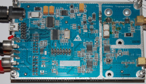
2. Transmitter
The transmitter schematic is located also on my Download page
Similar story like in RX part, but working in opposite direction:-) It had poor signal as zero IF (Audio) to 1296MHz conversion transmitter, but working nice as 28MHz/1296Mhz Up converter. Simple phase shifting RC network (it splits 28MHz signal going from transceiver to two 90 degrees shifted I/Q channels) has been added to suppress image channel.
The Transmitter board contains also embedded microcontroller that is controlling next parameters:
- Local Oscillator Frequency
- TX mixer DC balance (using serial DAC)
- RX-TX switching sequencer (to protect LNA from transmitted signal)
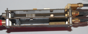
Transmitter PCB is stacked together with Local Oscillator (PLL) PCB.

Transmitter and Local Oscillator (PLL) + (Phase shift network) staked together

